Home » Posts filed under Carding
An Overview of Carding Cylinder
Bhavdip Paldiya Dept. of Textile Technology Sarvajanik College of Engineering & Technology, Surat, India Cell: +91 9662020909 Email: bhavdipk9009@gmail.com What is Cylinder: The carding cylinder is usually manufactured from cast iron, but is now sometimes made of steel. Most cylinders have a diameter of 1280-1300 mm and rotate at speeds between 250 and 500 rpm. Specification of Cylinder: - DIAMETER : 50”(120 mm)
- SPEED : 250-500 rpm
- WIRE POINT PER INCH: 550-650
- SURFACE SPEED: 1000ft/min.
- TOTAL WIRE POINT: 30lac
- WIRE POINT DIRECTION: Anti clock
Objectives of Cylinder: 1. Back plate: - To hold the fibre.
- To prevent the development of undesirable air current.
2. Top feather edge sheet: It controls the wt. & thickness of the flat strips. 3. Cylinder stripping door: This door is used to strip the wire point of cylinder. 4. Bottom sheet: - To hold the fibre.
- To prevent the development of undesirable air current.
5. Cylinder undercasing: - Remove dust.
- To maintain constant airflow.
Types of Cylinder: There are two types of cylinder. - Single cylinder
- Double cylinder
1. Single cylinder carding machine:  |
| Single cylinder carding machine |
Specifications - Cylinder Dia. 700mm
- Output: 100-250kgs/h
- Power: 18.5kw
Application - This machine can open various baled fiber,and send to next procedure via fan.
- It opens fiber with pin plate,high production and good quality
A brief feature of single cylinder:- Single Cylinder Carding Machine, up to 1.5 meters in diameter and up to 2.5 meters in width are produced as normal standard.
- Cover all types of fiber from very fine to very coarse fiber deniers; fiber lengths up to 120 mm can be processed. Both synthetic and natural fibers of all types can be processed.
- Cylinders up to 1.5 meters in diameter and up to 2.5 meters in width are produced as normal standard. Carding machines outside this size range can be discussed dependent on ard main cylinders are balanced to a surface speed of 1500 meters / per min.
- All types of carding machines both single and double doffers can be fitted with randomizer rollers or not dependent on customer’s needs.
- Card wires can be supplied as surface wound or interlocking as required.
- Card capacity is depending upon card type, fiber denier, types of fiber but can be excess of 800 kgs / per hour.
- Other details and variables dependent on customer’s needs can be discussed with our technical staff. clients’ individual requirements.
2. Double cylinder carding machine:  |
| Double cylinder carding machine |
SPECIFICATION : - ™ Middle cylinder diameter: Φ850mm,Φ635mm
- ™ Big cylinder diameter:Φ1230mm,Φ1020mm
- ™ Power:35KW
Application:- Double doffer used for carding and mixing opened chemical fiber and blending material.
New type of double carding m/c Specifications - Product Name - double cylinder carding machine
- Working width: 1800mm 2000mm 2200mm 2500mm
- Capacity: 150kg/h 200kg/h 300kg/h
- Dia. of cylinder: 1230mm
- Speed: 20 - 50m/min
Application: - Various kinds of fiber such as polyester,viscose,nylon,PP,fiberglas,etc
Cylinder Speed: - Higher cylinder speed helps fibre transfer. Higher the production, higher should be the cylinder speed.
- Higher cylinder speed improves carding action, thereby imperfections are reduced
Cylinder Wire Selection: Cylinder wire selection is very important, it depends upon cylinder speed, the raw material to be processed and the production rate. The following characteristics of cylinder wire should be considered. - Wire angle
- Tooth depth
- Wire population
- Rib thickness
- Tooth profile
- Tooth pitch
- Tooth point
- Overall wire height
Cylinder Wire Maintenance: - For a modern cylinder wire of 2mm height, grinding with the normal grinding stone is not recommended. It is better to use TSG grinder to grind the wire every 2nd or 3rd month, so that the sharpness of the wire is always maintained.
- TSG grinder does not grind the wire, therefore if the wire is worn out very badly the quality improvement using this grinding machine will be nil. Frequent grindings are recommended. If TSG grinder is not available, it is better not to grind 2mm wires.
- The number of traverse should increase depending upon the life of the wire. The number of traverse for successive grindings should be like this 3, 5, 10, 17 etc. Anyway the best method is to confirm with the microscope. If the grinding is not sufficient, the number of traverse should be increased.
Cylinder Construction in Modern carding The cylinders of modern carding machines are almost solely welded constructions (Fig. ). They consist of the shell reeled of metal sheet welded along its edges, bottoms with hubs stiffened with ribs, the shaft and the reinforcement rings. Such constructions are used by leading carding machine manufacturers, and particular solutions are different as to the side hubs construction and reinforcement rings  |
| Cylinder Construction |
Loads acting on the main cylinder of carding machine The loads acting on the cylinder result from: - The influence of fiFIBER on the teeth of card wire during the carding process; the forces are small and are omitted when calculating deflection of the cylinder shell,
- The construction deadweight and the centrifugal force; their influence on the cylinder deflection may also be neglected due to small rotational speed of the cylinder (circa 100200rpm),
- Reeling at tension of the metallic card wire.
 |
| Tension forces acting on the metallic card wire coils |
Reeling at tension S and the reeling pitch t of the card wire on the cylinder with the radius R (Fig. 3) exerts pressure on the cylinder shell directed radially inward with the value of - Radial pressure = pr
- Force =F
- Surface force =px
Setting between cylinder and doffer If the setting between cylinder and doffer is very close, the wires will get polished and this will affect the fibre transfer. If the setting is too wide, the fiFIBER will not be transferred to doffer from the cylinder, hence cylinder will get loaded. While processing synthetic fiber cylinder loading will badly affect the yarn quality. Moreover, it is difficult to improve the wire condition if the loading is severe. The only solution would be to change the wire. Therefore enough care should be taken while processing synthetic fiber.  |
| Setting between cylinder and doffer |
The setting between cylinder and flat - The most critical setting in a carding machine is between cylinder and flat tops. While processing cotton, it can be as close as 0.175 mm provided the mechanical accuracy of flat tops is good.
- Closer the setting between cylinder and flats, better the yarn quality. Neps are directly affected by this setting. Of course, very close setting increase the flat waste. For processing cotton the setting can be 0.25, 0.2, 0.2, 0.2, 0.2mm. For synthetic fiber it can be 0.3, 0.25, 0.25, 0.25, 0.25mm.
- The setting between cylinder and flats can be as close as possible.
 |
| The setting between cylinder and flat |
Heal and Toe Arrangement The top half of the cylinder is surrounded by a series of flats. The flats are also covered with wire teeth, the points of which oppose & are set close to the wire on the cylinder. The setting between flats & cylinder is arranged that there is a wide3r setting at the back or trailing edge on which cotton first reaches for being carded & closer setting at the leading edge where the cotton leaves the flat. This arrangement is generally termed as ‘Heal & Toe’ arrangement.  |
| Heal & Toe’ arrangement |
Importance: The object of this type arrangement is to effect a gradual opening & carding of the fibers at each flat.
Chute Feeding or Aero Feed System in Carding
Bhavdip Paldiya Dept. of Textile Technology Sarvajanik College of Engineering & Technology, Surat, India Cell: +91 9662020909 Email: bhavdipk9009@gmail.com Chute Feed System:
Chute feed is a system of feeding small tufts of cotton fibres directly from blow room to a series of cards, arranged in a circuit through pneumatic pipe. A condenser in the pneumatic pipe sucks the material from blow room and delivers it to the flock feeder through pneumatic pipe by way of the filling trunk.  |
| Chute Feed System |
Photo electric cell in the filling trunk regulates the supply of material from blow room. From here, the material is fed to the kirschner beater by way of two ridged roller and two feed rollers. Krischner beater open the cotton into desired size tufts. A fan blows the tufts from the kirschner beater into horizontal c closed circuit loop situated above the cards. The return trunk has the duty of returning the surplus material(after the supply to last card) to the beater that also of uniting well opened material with supply of fresh material thus delivering it directly to the horizontal duct again. The separating head arranged in the horizontal closed circuit loop divert the part of tufts from air current into vertical feed chutes above the card inlets. Vertical feed chute ensures a uniform supply of material over the full working width of the card. Uniform separation of the tufts from the air current is achieved by adjusting the nose in the separating head. Raising the leading edge produces more separation and vice versa. The weight of the card feed per meter depends on the static excess pressure in the installation. This drops practically linear from separator to separator by about 2mm head of water. The weight of the feed per unit length must be adjusted in accordance with this drop by increasing or deducting the distance between the glass front and the rear wall of the feed chute. The weight per meter ranges between 600 to 700 gms. Thus while deviation of the card sliver count from one card to another must be regulated with the glass plate. The specific count of the sliver itself must be adjusted with the count change wheel. Card Feed Chute: The feed weight at the card depends on the static pressure in the aerofeed system and the chute depth adjusted. Since the pressure diminishes from one feed chute to another, the chute depth must be matched accordingly. It can be varied from 80 mm to 120 mm and is read off on the scale at the arrow mark. THEORY AND LITERATURE The blow room machinery is linked to the cards by trunking and the opened cleaned cotton is conveyed by pneumatic means to each card – this the principle of chute feed system. The basic elements of chute feed system are : - Conveyor system to carry material from B/R to group of cards with the help of air.
- Proper control of air pressure in the conveyor system for smooth flow of material.
- A mechanism to feed the material at uniform weight per unit length and width.
- A delivery system to feed the material to the card feed roller.
- A sensing mechanism at chute to keep a certain amount of material as reserve and also to control the feed of material to the chute.
Present Development : Automation – bale to cone : continuous automated spinning (CAS) in Japan - Platts chute feed system type 685
- Exact feed FBR chute feed system by trutzschler, germany
- ML snowflaker chute feed by U.S.A
- NSE chute feed system of bombay
- Vibra chute DS by W,.Germany
- Rando level feed by U.S.A
- Transautomal by Italy
- Aerodome by Switzerland
Views of Indian Mills : The only reservation that seem to have is that its introduction in the processing line may result in high yarn count variations. This should not be so since C.F system has gained good acceptance in all the textile mills in advanced countries. Lap Feed Demerits: - Stoppage due to lap changes.
- Extra labour for lap trasportation
- Compression of fibres in the lap poses problem during opening in carding.
- More wastes due to lap tails and damages.
- Irregularity of sliver weight due to improper unwinding of laps.
Chute Feed Merits: - Direct automatic feed to card increases B/R working efficiency.
- Elimination of Man power during scutcher operation.
- Processing of rejected lap is avoided.
- Due to loose form of feeding of fibres trash particles can be removed easily during carding.
- Suitable for synthetic fibres of bulky in nature, avoiding
Advantages of flock feeding or chute feed system : - The automatic continuous feed directly linked to the blow room eliminates the lap formation. This increases the working efficiency of the blow room.
- The main power requirement in doffing the lap, weighing, transportation to card and feeding at the card is eliminated.
- The processing of rejected laps in the blow room is avoided.
- The fibres are fed to the card in loose sheet form as against compressed form so that trash particles can be easily extracted from fibres by the carding action.
- Excessive sliver irregularities due to the lap licking during high humidity, double lap feeding, lap splitting, lap piecing etc, are eliminated.
- When compared to lap fed, there is a reduction of 1 % CV flock feeding card sliver.
- Crushing of foreign materials seed bits and other trash particles during calendering and difficulty of removing a subsequent processes is reduced.
Disadvantages or limitations of chute feed system : - Blow room should run the same number of hours per week as the cards do.
- The card production must be kept excessive to assure continuous feed to drawframe at the time of stoppages at blow room due to maintenance and other unavoidable problems.
- Chute feed system control short term variation but not the medium and long term variations.
- A reliable check on the nominal count can be established in lap forming system by controlling total lap weight and C.V. value of the weight per unit length. There is no such control in the chute feeding system.
- Change of mixing will result in more waste in chute feed.
An Overview of Doffer in Carding Machine
Bhavdip Paldiya Dept. of Textile Technology Sarvajanik College of Engineering & Technology, Surat, India Cell: +91 9662020909 Email: bhavdipk9009@gmail.com What is Doffer? Doffer is a revolving cylinder, or a vibrating bar, with teeth, in a carding machine, which doffs, or strips off, the fiber from the cards. 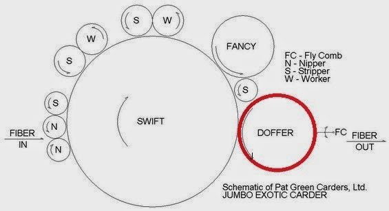 |
| Doffer in carding machine |
Object of Doffer: The main object of the doffer is to take off the fibres that lie more or less evenly distributed between the cylinder wires, and to condense them so that they constitute a coherent web. Types of Doffer: There are two types of doffer in carding. - Single doffer
- Double doffer
Specification of Doffer: - DIAMETER:-27’’dia
- SPEED:-45rpm/minute
- WIRE POINT PER INCH:-300-400
- SURFACE SPEED ratio:-53.3
- DIRECTION:-CLOCKWISE
Doffer Wires: The doffer strips the fibres from the cylinder. The rate of transfer is called the transfer ratio. The transfer needs to be optimised to reduce the re-circulation on the cylinder to a minimum. The specification of the doffer wire, together with the card settings will define the correct operation of the transfer of the fibres from doffer to cylinder. Doffer Wire Maintenance: - Doffer is still working with a concept of Land formation. A normal grinding machine will be good for doffer grinding. All the wire points should be touched by the grinding stone. A slow and gradual grinding with the grind-out concept will give the best results. Harsh grindings will result in burr formation on the land. This will increase the number of hooks in the fibre; thereby the effective length of the fibre from this card will be reduced.
- Flat tops grinding is very important. Every time a flat top is ground, yarn quality is improved. It is better to use a grinding machine with the emery fillet. Frequent flat tops grinding will result in less neps and the yarn quality will be consistent.
- Some mills increase the life of the flat tops compared to cylinder wire. But it is better to change flat tops and cylinder wire together for better and consistent yarn quality.
- It is a good practice to check the individual card quality before changing the wire
Uses and Characteristics of Doffer: Suitable for carding of 1.5D-20D*38-65mm artificial fiber. Single cylinder high-speed carding and double-doffer outputting has high production capacities. Cotton stripping has been used stripper bar,the cotton feeding roller is controlled by frequency conversion.
An Overview of Flat- Element of Carding Machine
Bhavdip Paldiya Dept. of Textile Technology Sarvajanik College of Engineering & Technology, Surat, India Cell: +91 9662020909 Email: bhavdipk9009@gmail.com FLATS Together with the cylinder (Fig.), the flats form the main carding zone. Here, the following effects should be achieved: - Opening of tufts into individual fibers;
- Elimination of remaining impurities;
- Elimination of some of the short fibers;
- Untangling neps (possibly their elimination); dust removal
- High degree of longitudinal orientation of the fibers.
 |
| Flat in carding |
Construction of the Flats The bars of the flats are made of cast iron and are somewhat longer than the operating width of the card, since they rest on adjustable (so-called flexible) bends to the left and right of the main cylinder and must slide on these guide surfaces. Each bar is approximately 32 - 35 mm wide (might change to smaller widths). The bars are given a ribbed form (T-shape) in order to prevent longitudinal bending. A clothing strip (108 b) of the same width is stretched over each bar and secured by clamping, using clips (c) pushed onto the left- and right-hand sides of the assembly. Since some space is taken up by the upper edge of each clip, only a strip about 22 mm wide remains for the clothing (hooks or teeth). For this reason, the flats do not enable an absolutely continuous carding surface to be formed above the cylinder; there are gaps between the clothing strips. The flats as used on the flat type carding machine designed for processing cotton and fibres of similar staple length to cotton may be fixed in relation to the carding cylinder or part of a chain of revolving flats which move around part of the circumference of the carding cylinder. Types of Flat:Flat are two types….
- Revolving flat
- Stationary flat
Revolving flat Conventionally, the revolving flat is T-shaped and made of cast-iron, machined to accept a top of card-clothing attached to its flange by steel clips, each end of the flat being machined for correct location of the flat in close proximity to the carding cylinder, against which the card-clothing top has to operate. The rib of the flat is designed to provide the necessary stiffness to enable the flat to span the width of the carding machine and ensure that an equal setting of the card-clothing on the flat to that on the carding cylinder is sustainable over the working width of the cylinder. Stationary flats Stationary flats can be used in addition to revolving flats or can be entirely substituted for revolving flats, such stationary flats being conventionally also T-shaped in the form of an iron casting or an aluminium extrusion. The flange carries a card-clothing top or other operative element such as a trash extracting knife which is clipped or attached by screws to the surface of the flat, and the rib is designed to support the flat correctly across the width of the carding cylinder. The ends of the flat are machined to accept the setting and securing arrangements for fixing the flat to the carding machine frame in its required relationship to the carding cylinder. With both stationary and revolving flats, when the card- clothing top or other operative element becomes worn out or damaged, it is removed from the flat and a new top or other element is clipped or screwed to the flat in replacement. Replacement of the card-clothing top which is conventionally clipped or bonded to the revolving flat involves the use of specialised machinery which adds to the cost of the replacement. Replacement of the top which is screwed to the flat requires investment in the specially designed flat adapted to receive a screw-on type of top. Movement of the flats The bars of the flats mesh individually, like an internally toothed wheel, with the recesses in a sprocket gear, and are carried along by rotation of the sprocket. The ends of the bars of the operative flats slide over a continuous bend – with metal-to-metal friction. As the flats move at a very low speed compared with that of the cylinder in principle, the flats can be moved forward or backward, i.e. in the same direction as or in opposition to the cylinder. If the flats move with the cylinder (forward), the cylinder assists in driving the flats and the removal of strippings is easier. Forward movement therefore gives design advantages. On the other hand, reverse movement (against the cylinder) brings technological advantages. In this system, the flats come into operative relationship with the cylinder clothing on the doffer side. At this stage, the flats are in a clean condition. They then move toward the licker-in and fill up during this movement. Part of their receiving capacity is thus lost, but sufficient remains for elimination of dirt, since this step takes place where the material first enters the flats. At that position, above the licker-in, the cylinder carries the material to be cleaned into the flats. The latter take up the dirt but do not transport it through the whole machine as in the forward movement system; instead, the dirt is immediately removed from the machine (directly at the point where the flats leave the machine).
An Overview of Licker-in (Taker-in) in Carding
Bhavdip Paldiya Dept. of Textile Technology Gujarat Technological University, Gujarat, India Email: bhavdipk9009@gmail.com
Licker-in: A roller on a carding machine, especially the roller that opens the stock as it is fed into the card and transfers the fibers to the main cylinder. Licker-in also known as Taker-in.  |
| Taker-in |
Basic Function of Licker-in: - To open the cotton into very small tufts.
- To extract the seed bits, sand and other vegetable trash particles from cotton.
- To transfer the cotton into the cylinder surface and distribute the fibres as evenly as possible both transversely and longitudinally on the cylinder surface.
- The roller that receives fiber from the feedroll(s) is called the licker-in.
- The licker-in rotates upward as it takes fiber away from the feedrolls.
- If a card has a feedroll/feedplate feeding the licker-in, the licker-in rotates down to comb the fiber off the nose of the feedplate.
- As the fiber mixes in the card, the web coming out of the card will appear grey.
Better Function of Licker-in: - Normally the setting between the feed plate and Lickr-in is around 0.45 to 0.7mm, depending upon the feed weight and fiber type.
- The setting between Licker-in and the first mote knife is around 0.35 to 0.5 mm. This helps to remove the heavier trash particles and dust. Closer the setting, higher the wastage.
- The setting between Licker-in and combing segments is around 0.45 to 0.6mm. This helps to open the material.
- Some cards have two mote knifes in the Licker-in under casing. The setting is around 0.4 to 0.5mm. This helps to remove the smaller trash and dust particles
- In order to maintain the licker-in area working with high performance, we recommend timely replacement of licker-in wire. Spinners benefit through better carding results (higher nep and trash removal, lower number of Classimat faults) as well as higher lifetime of cylinder and tops.
- Higher Licker-in speed for coarse fibers and dirty cotton helps to remove the trash and improves the yarn quality.
- The concept of using three licker-in place of one is basically for better cleaning of the feed material. Here the concept of clamped and unclamped feeding is used.
 |
| Function of Licker-in |
Pinned Licker-in: - Also known as “Fibre Friendly”
- Stewart developed the Pinned Taker-In in 1972, and extended use since then has shown it to be fibre-friendly and extremely durable, making it an ideal match for TRUTSCHLER High Production Cards, where quality and output must be maximised and downtime minimized.
- Cotton has been traditionally carded using card wire. However, pins with their smooth pointed shape, do less damage to the fine fibres.
- The sharp, but smooth point of the pin gives excellent fibre penetration.
- The grain of the metal and the machining marks of the pin all run along the axis of the pin, so fibres can float freely around the point, and there are no traps to catch fibres or start wear.
- A reduction in fibre damage and improved waste extraction are usually found.
- This can recoup the cost of a Pinned Taker-In over its first year of three shift working
 |
| Pinned wire Card wire |
A close up view of a Stewart Taker-In which had run 3 shifts for 8 years in a mill in Germany. It was still running well after this demonstration of longevity, and was only removed for exhibition purposes Efficiency of Pinned Taker-In Compared with Wire. Efficiency is consistently high throughout the extended life of a Pinned Taker-In. The efficiency of a wire Taker-In drops so rapidly that the wire must be replaced regularly. Advantages of Pinned Taker-in: 1. Universal Pinning A major advantage of the STEWART Pinned Taker-In is that one specification of pinning can be used to successfully card almost all fibres, so there is no need to change when running different fibres or blends. 2. Reduced Maintenance: Less Down time Regular card down-time is saved because it is not necessary to rewire a Pinned Taker-In. This is particularly important for the Taker - In. which is usually rewired three times as often as the cylinder. The pins wear better because of their points, and they do not need sharpened or ground. Grooved Wires by Reiter: - Grooved licker ins are mostly used on (older) slower cards.
- The front angle is dictated by the application.
- Cotton is carded with 10° front angle (carded and OE applications) or with 5° (combed cotton mostly, using long and fine cotton fibres).
- For synthetics, we have grooved lickerin wire with 0° front angle.
- Grooved lickerins are available in several rib widths to suit particular cards.
- Grooved lickerins can be supplied in Super or Duratech steel.
- Duratech is our recommendation to achieve best performance and lifetime on grooved lickerins.
Interlocking Wires by Reiter: - Interlocking can be used to convert worn out grooved lickerins.
- Modern, high-speed cards are using interlocking lickerins. The specification
- For interlocking licker in is in the most cases card specific, with the
- Full range being offered by Bekaert Carding Solutions. Interlocking licker in
- Wires are available in Super, Duratech and Ultra. We recommend
- The use of Ultra interlock licker in wires to achieve the best carding performances.
Licker-in by Bakaert: - Most modern cards have stationary (or fixed) flats under the lickerin.
- Bekaert Carding Solutions offers the XLSA Fibre Saver system to mount in this
- Position on cards with 10 inch lickerin rollers.
- The XLSA-system is a workproven fixed flat system.
- Its function is to:
- Subject the fibre tufts from the feed plate to intensive preopening and cleaning by the two stationary flats and the knives mounted in the XLSA system.
- Ensure that trash is eliminated and that only a minimum of good fibre is taken out with the waste.
Benefits: - Reduces good fiber loss under the lickerin.
- Increases the removal of trash and unwanted particles.
- Removes fibre chips and fused fibres from synthetic fibres.
- The DT-type fixed flats can be easily exchanged and set to keep the XLSA system in good operating condition.
- Pre-opening and cleaning mproves the lifetime ofylinder and top.


